

When a sheet metal component is folded, the material around the bend does more than simply change direction. Metal on the outside of the bend stretches, while material on the inside compresses. If a bend line stops next to another flange, corner or solid section of the part, those forces need somewhere to go.
That is the purpose of a bend relief.
A bend relief is a small cut-out placed at the end of a bend line. Although it may appear to be a minor feature in the flat pattern, it can make the difference between a clean, repeatable folded component and one with tearing, distortion or an untidy corner.
A rounded relief gives the bend a controlled termination and avoids leaving a sharp internal corner.
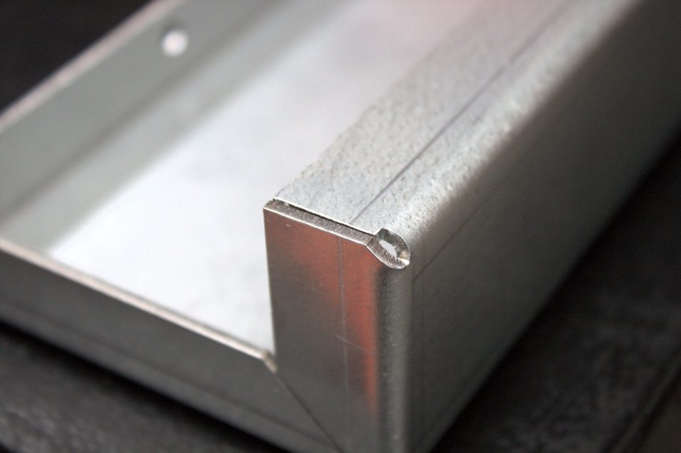
Processes: Laser Cut, Sheet Metal Folding
Detailing: Tight folds, bend reliefs
What happens when a bend has no relief?
During press brake folding, the material within the bend zone is being plastically deformed. If the bend runs all the way to a free edge, the surrounding material can usually move without causing a problem. Difficulties arise when the bend stops part-way across the component or meets an adjacent feature.
Without enough clearance, the material at the end of the bend can be pulled in competing directions. Depending on the design, material and thickness, this may cause:
- tearing or cracking at the corner;
- a pinched or raised edge;
- distortion in the neighbouring flange;
- an uncontrolled notch created by the forming process;
- inconsistent dimensions between components; or
- a corner that requires additional dressing or welding.
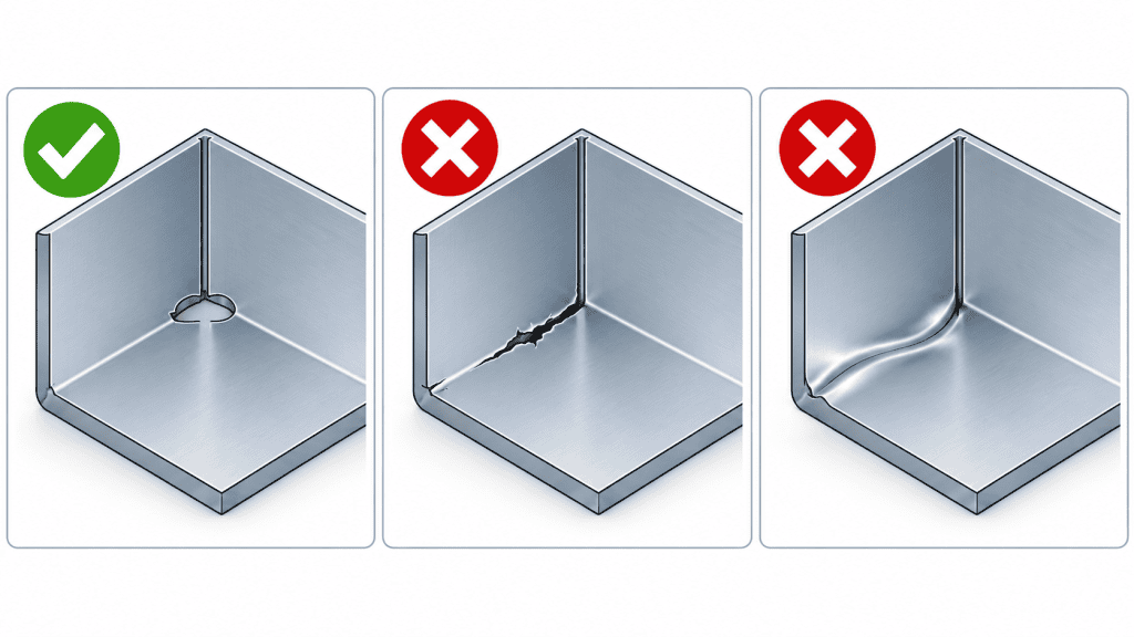
When the bend zone runs into retained material, the corner can split or distort rather than forming cleanly.
Adding a suitable relief allows the two areas of material to move more independently. The laser-cut profile defines exactly where the bend should finish, rather than leaving the press brake operation to create its own path through the corner.
Where are bend reliefs normally required?
Bend reliefs should be considered whenever a bend line terminates next to material that is not intended to form with it. Common examples include:
- trays, boxes and folded enclosures;
- brackets with local tabs or return flanges;
- bends that stop before the end of a component;
- intersecting bends at a corner;
- narrow flanges beside a larger folded section; and
- folded features close to holes, slots or other functional details.
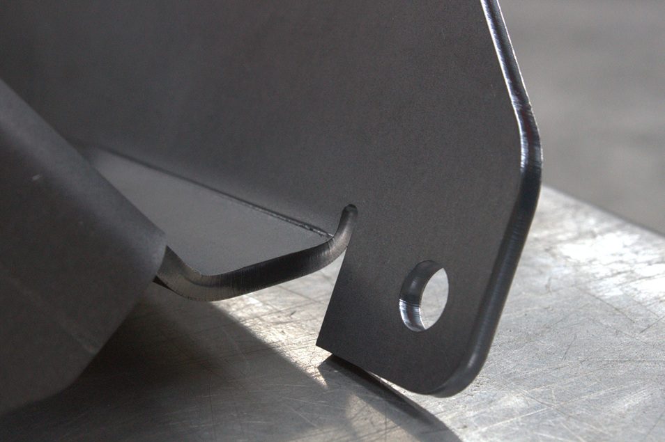
Processes: Laser Cut, Deburred, Sheet Metal Folding
Detailing: Smooth consistent edges for industrial brackets.
The second photograph shows a more generous relief separating a local flange from the adjacent folded section. The rounded end also removes the sharp internal corner that a simple square-ended slot would introduce.
A relief can isolate adjacent features so that each fold forms without dragging or tearing the material between them.
A relief is not automatically needed at both ends of every bend. Where a bend finishes at the external edge of the blank and the neighbouring geometry is free to move, adding one may serve no useful purpose. The decision should follow the actual bend zone and the way the surrounding material will behave during forming.
What shape should a bend relief be?
Rectangular, obround and round-ended reliefs are all commonly used. The best choice depends on the component, its intended use and any visual or hygiene requirements.
Round-ended and obround reliefs are often useful because they avoid the pronounced stress concentration created by a sharp internal corner. A rectangular relief may be perfectly suitable where space, appearance and loading permit it, but its internal corners should still be considered carefully.
The relief must also be large enough. As a practical starting point, its width is often at least equal to the material thickness, while its depth must extend beyond the area that will be deformed by the bend. A commonly used initial guide is to take the relief beyond the bend zone by considering both the material thickness and the intended internal bend radius.
These are design starting points, not universal manufacturing limits. The correct dimensions depend on:
- material type and grade;
- sheet thickness;
- internal bend radius;
- bend angle;
- grain direction;
- tooling and V-die opening;
- nearby features; and
- the functional and cosmetic requirements of the finished component.
For example, aluminium, mild steel and stainless steel of the same thickness do not necessarily behave in the same way. A relief that works on a light-gauge enclosure may also be unsuitable for a thicker structural bracket.
Bend reliefs should be designed into the flat pattern
The most reliable time to resolve a bend termination is before the component reaches the laser.
When the relief forms part of the CAD model and flat pattern, it can be laser cut accurately and repeated consistently across a batch. Trying to correct the problem after folding may involve manual cutting, grinding, welding or redesigning the part—all of which add time without improving the original design.
It is also important to supply the complete manufacturing information at quotation stage. A 3D model helps us understand how the component should look after folding, while a drawing can identify material, thickness, critical dimensions, tolerances, finish and any features that must remain visually clean.
As explained in our laser cutting design guide, a part should be considered as a complete manufacturing route rather than treating the laser-cut profile and subsequent operations in isolation.
Designing for manufacture, not simply for the screen
A folded model can look perfect in CAD while still containing a bend termination that is difficult to manufacture cleanly. Software may unfold the part without warning, but it does not always account for the exact material behaviour, tooling access or finish expected from the real component.
Early manufacturing review helps identify these issues before material is cut. In some cases, the answer is a conventional bend relief. In others, the better solution may be a change to the flange geometry, bend radius, corner detail or folding sequence.
Yorkshire Profiles provides laser cutting and CNC sheet metal folding from the same York facility. Keeping these processes together allows the cut profile, bend geometry and later fabrication stages to be considered as one job—from one-off prototypes through to repeat production.
Need us to review a folded component?
If you are unsure whether a part needs bend reliefs, send us the 3D model and drawing before placing the order. Our team can review the bend terminations alongside the material, thickness, radii and other operations required.
Upload your drawings through our online enquiry form or email sales@yorkshireprofiles.co.uk. Providing the material grade, thickness, quantity and finish at the same time will help us assess the component and prepare an accurate quotation.


