Producing laser cut parts is a straightforward process providing it is done correctly from the start. It is frustrating for both client and supplier when parts are received and they are not what the client desired, it is even more frustrating when it is discovered the inaccuracies are caused by issued drawings. Although quality checks of customer issued drawings will 99% of the time pick up any inaccuracies, there is unfortunately always the 1% that slips through due to human error.
It is possible however that such inaccuracy could be prevented completely with just a few checks before any drawings are issued.
Scaling Problems
The most common error is due to scaling of parts. Drawings produced in AutoCAD should always be drawn full size in the model space, there is no reason to be scaling parts up or down (printed copies can always be fitted to the paper-size regardless of the size they are drawn, this can be changed in the paper space). If scaling has to be used, always state what scale has been used and include dimensions on the drawings so this can be checked in the received file.
If providing a drawing which has not been produced in AutoCAD, make sure to include at least 2 dimensions. A horizontal dimension and a vertical dimension will help us to ensure the part is drawn correctly on both axis.
Broken Lines
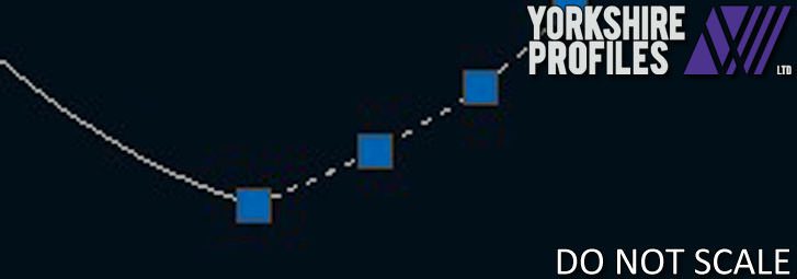
The next common errors are produced when a file has been produced in software other than AutoCAD or has been traced / converted from a non vector drawing (bmp or jpg). Sometimes converting files and tracing files produces anomalies such as double lines and very small broken lines. Although our software is designed to pick up on these anomalies and prevent them from being cut, it does add processing time to the quote or order due to us having to tidy up the CAD work.


Usually the small lines have to be joined up to produce the best quality cut, so rather than a curve constructed of hundreds of small straight cut lines, the curve is produced using a smooth polyline (‘Spline’).

Although the vast majority of any drawing inaccuracies do not reach production stages, it causes delays to quotes and orders which could be otherwise prevented and worst-case scenario result in delays caused by communication back and forth to confirm scaling details of multiple parts.

